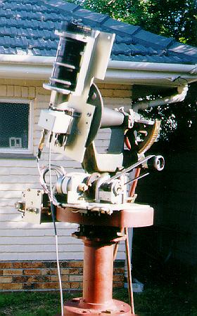
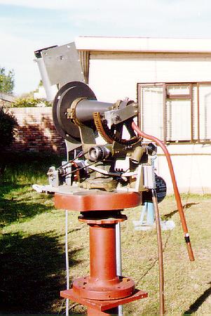
My automated satellite tracking setup consits of a motorised mount carrying a low-light surveillance camera (small white box) fixed behind an old TV camera telephoto lens.
Updated : 21 June 2000
I retired at the end of October 1999 and for the first two months enjoyed myself by doing nothing. Then in December Willie told me about a local source of CCD cameras and I went and purchased one. After battling with trying to line up a telescope on a celestial object by sighting along the tube on my hands and knees (and battling to get back onto my feet subsequently) I thought of building a computer controlled system. I knew nothing about stepper motors other than that they could possibly do the job. I remembered Willie showing me a simple electronics circuit to control such so I paid him a visit and he gave me a copy of his circuit diagram and the source code for his elementary control program.
Originally I planned to write all my own software but Willie tackled the task with such enthusiasm and efficiency that I soon lost track of keeping up and have now left the task entirely up to him since he is a far superior programmer than I am. After that there was no looking back and I have now achieved what I said I was going to do - operate my telescope remotely and in comfort!
|
My automated satellite tracking setup consits of a motorised mount carrying a low-light surveillance camera (small white box) fixed behind an old TV camera telephoto lens. |
The video unit currently in use is a KSC-16SC CCTV camera. This is a black and white low light level (0.05 lux) surveillance camera, approximately 57 x 52 x 55 millimetres in size and containing a 1/3 inch Sony CCD chip. It is fitted with a C/CS lens mount but since I wanted to use it on a telescope and the lenses available were not really suitable for my purpose (or pocket) I did not purchase any lenses. The unit gives out composite video and is powered by 12v DC at about 1.5W. From details of other CCD video cameras available on the Internet it appears very similar to the PC23C but is not identical so modifications to the PC23C cannot be applied to the KSC-16SC. It has no controls/adjustments and uses an automatic electronic shutter ranging from 1/50th second to 1/100000 second and is apparently controlled by the light intensity. The limited literature that comes with the unit (a small piece of paper) describes it as a 1/3 inch interline transfer CCD (it is not possible to identify the chip without unsoldering several components) complying with CCIR (PAL) or EIA (NTSC) standards. For CCIR the pictures elements are 537(H) x 597(V) and for EIA the values are 537 (H) x 505 (V). The scanning system is CCIR with 625 lines and EIA with 525 lines using a 2:1 interlace. The sync system is internal and the horizontal resolution is 420 TV lines. Sensitivity is given as 0.05 lux at F1.2. Gain is AGC with a S/N ratio better than 48 dB. The video output signal is 1v p-p at 75 ohm load and operating temperature range is -10° C to 50° C. No manufacturer identification is given other than made in Taiwan.
A 0.02 lux unit is also available locally and will be purchased once funds permit it. Hopefully this will provide an extra magnitude gain.
Other smaller camera lenses are available but have not yet been tested.
The ultimate intention is to use a 12 inch f/5 reflector but this is some time in the future as a suitable mounting has still to be constructed as the current mounting cannot support a telescope this large. The field of view will be about 11.5 x 8.7 arc minutes
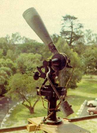 An old picture of my mount showing what it looked like about 30 years ago, here carrying the original 5" Apogee refractor, an alternative still to be tried. |
The mounting used was originally supplied by the Smithsonian Astrophysical Observatory as part of their MOONWATCH program. It was designed for gun laying in the US military and was manufactured by Bausch and Lomb. These are very scarce and unlikely to be generally available but may be found in the hands of retired MOONWATCH'ers. This should not be a handicap as any type of alt-azimuth mounting can be easily motorized - it will just take a little head scratching as to how best to mount the stepper motors.
The unit is well constructed and rather heavy. The azimuth component consists of a large brass gear of 320 teeth against which meshes a spring loaded worm. This is mounted horizontally on a length of piping embedded vertically in concrete into the ground. Attached to the worm is a handle which was originally turned by the operator but now by a stepper motor. The azimuth gear is graduated in milli-radians (6400 divisions = 360° so 1° = 17.777777 mils). The elevation shaft is a cone fitted between two uprights mounted on a base plate which rides on a vertical cone in the centre of the azimuth gear. One side of the upright has a mounting plate for equipment and the other side has a bar fitted with a movable counterweight so that the equipment fitted can be balanced. On the same end of the elevation cone is a gear driven by a worm turned by a handle originally operated by the observer but now moved by a stepper motor. This is spring loaded and the quadrant gear has 32 teeth and is also graduated in milliradians.
The two spring loaded gears caused problems with the stepper motors since they did not provide a constant friction load which caused the motors to stall too easily. Both worms were then modified slightly by providing an extra bearing point so that they could no longer "rock" against the gear and this provided a much smoother drive.
By means of suitable gearing (ie what's available in the junkbox) the elevation and azimuth drives worms were attached to the stepper motors which had to be mounted on the azimuth base plate so that they are carried around on the head when the mounting is moved. This is not an ideal situation as the stepper motors vibrate and this is transferred to the image. After several attempts at various ways of mounting the motors this problem has been overcome and vibration is no longer a problem for most satellites.
In order to get a smooth stepping motion (half stepping is currently used on both motors) it was eventually found that toothed belt drives gave the best results. The belts are not tightly stretched as this can cause stalling so the looseness in the belts helps with gears being off-centre, non squared on etc. There is also some "play" which has not yet proved a problem due to the size of the field of view - this could probably be corrected by the software if necessary.
One has a lot of leeway in designing a tracking system as it depends on what speed your stepper motor can run at and what gearing is necessary to slow things down a bit. Since satellites move at a wide variety of speeds the demands can be quite severe and it may take some experimenting to end up with a system that is satisfactory. After several attempts this is what I have finally settled upon (for the moment!):
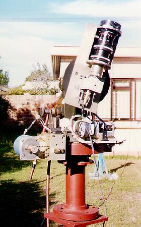 From this angle the azimuth drive motor (lower, left) is clearly visible. The cable run can also be seen dissapearing into my observing room. |
azimuth :
elevation :
My present mounting made the tracking requirements more severe than usual due to the fact that the gearing system built into the mounting slowed things down a lot. Consequently one has to gear up the speed of the stepper motors and run the motors as close to stalling speed as possible to get maximum speed. When I construct the mount for my 12 inch telescope I will probably use a mechanical system similar to that used by Mel Bartels and friends in driving their telescopes.
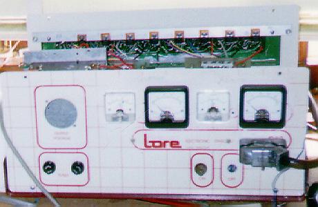 My electronics interface box includes the stepper motor power supplies and electronics for driving the two motors with meters reading their drive currents. A re-used heatsink with its power transistors from an old printer can be seen fitted to the back. The connector and cable (below, right) connects to the telescope drive outside. |
In my case I originally used the electronics out of a wide carriage printer - stripping out the unnecessary components after tracing out the critical bits needed to drive the stepper motors and also using the power supply - in fact early versions of the satellite tracking system used the stepper motors out of the printer, but the elevation stepper was eventually changed as outlined earlier.
Before rushing out to buy components etc see what you have in any old printer you can lay your hands on - most of the electronics is already present and can be easily modified for your specific needs.
A replacement for the azimuth motor is now being considered and for this an entire new electronics system is being constructed as the new motor needs 2.5 volts at 4.8 amps. Hopefully this will provide plenty of torque so the azimuth speed can be increased.
The software developed by Willie is called CoSaTrak and is written in Pascal. Besides being able to calibrate the mounting, the program can locate and track astronomical objects and of course track artificial satellites in several modes.
Fuller details on the program are given in Willie's contribution - who better able to describe it than the artist himself?
Audio commentary is given during a tracking session with time signals in the background and this is recorded on the video tape which makes things easier for later analysis etc.
A fair bit of testing etc remains in this area. Ideally I would like to capture a field showing the satellite against a background of stars at a known time. Using second party software such an image could be overlaid on a star chart - such as provided by the excellant program GUIDE and several others - and the coordinates of the satellite read off to provide a time and position that can be used in orbit determination.
 Rotated by 180° in azimuth reveals a better view of the altitude drive showing the belt drive to the worm and gear. The weight from the counterweight stork has been removed since it is not needed when the lens is mounted. |
A fair percentage of satellites produce flares or specular reflections and these can be studied in greater detail if required. Positional work has not yet been tried - due to lack of time - but is is sometimes obvious that the orbital data is not that accurate - its very easy to determine the culmination elevation and thus compare it against that predicted.
Occassionally one has extra thrills - in one case we recorded the satellite EGP crossing the crescent moon - we could not actually see the satellite against the moon as the moons brightness just produced a big white "blob". Also frequently seen are non-predicted satellites which are usually easy to identify later as one has the time and bearings from reading the display on the screen. (Some footage made into animated GIFs are here.)
Another option we wish to pursue is the imaging of satellites such as Mir, ISS or the shuttle etc. This has been done quite succesfully by others and we see no reason why our system cannot do the same. It does of course mean using higher powered telescopes etc so this will be one use for the 12 inch telescope.
I have always been fascinated by satellites in very elliptical orbits with high apogees, geostationary and near-geostationary satellites etc so this will be another use for the larger telescope. Again its a case of the telescope and not the software being the delay in implementing this application.
Some other options that will no doubt be added in the course of time are
Its great to sit in a comfortable armchair in a warm room and watch a satellite being remotely tracked on a monitor whilst a cold wind blows outside - its FUN and that's what a hobby should be.
Finally I would like to express my thanks to Willie for his help and encouragement. By nature I am very lazy but with Willie's enthusiasm and drive he has kept me busy and I have thoroughly enjoyed my first six months of retirement and look forward to doing more exciting things with his program.
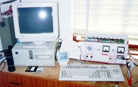 My "satellite tracking control centre" (not showing the monitor and VCR) seen here during its development stages. |