 |
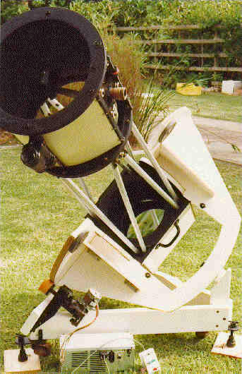
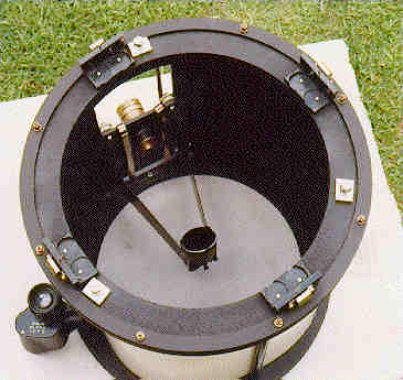
The top-end of the telescope can be rotated to always have the eyepiece in
a comfortable viewing position. The sled type focussor enables the whole
secondary mirror together with eyepiece to move closer or further away from
the primary to achieve focus instead of the usual way of racking the
eyepiece in and out. This was necessary because the relatively small size
of the secondary mirror requires the eyepiece to be very low down onto the
telescope tube. When required to do astrophotography, the focal plane does not reach to
the film with the secondary in it's normal viewing position. With a sled
focussor the secondary can be moved closer to the primary to get the focus
to reach out to the film plane at the expense of a little light loss round
the secondary. Read here to see how I determine focus and calculate exposure time for astrophotography. |
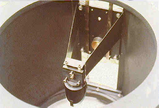 |
The secondary mirror mount allows total freedom of adjustment in order to achieve collimation which can be quite tricky when allowing the top end to rotate. Only two secondary supports, connected directly to the sled, fix the position of the mirror w.r.t. the eyepiece. A pair of constant force springs take out any backlash that might exist in the focusing adjustment. |
 Schematic showing the secondary mirror mounting and sled focussor arrangement. The sled is drawn in the optimal focus position where all the light from the primary is captured by the secondary giving an idea of how close the optimal focal plane position is. By screwing the (green) focus knob down, the focus is moved out, resulting in some light loss. Apart from the standard 3-point adjustment, the secondary mirror's position can also be ajdusted up/down and in/out for collimation and centering by slotting the holes of the screws containing springs. Schematic showing the secondary mirror mounting and sled focussor arrangement. The sled is drawn in the optimal focus position where all the light from the primary is captured by the secondary giving an idea of how close the optimal focal plane position is. By screwing the (green) focus knob down, the focus is moved out, resulting in some light loss. Apart from the standard 3-point adjustment, the secondary mirror's position can also be ajdusted up/down and in/out for collimation and centering by slotting the holes of the screws containing springs. |
|
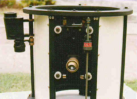 |
The focus adjustment is done by means of the captured plastic nut (green above), connected to the sled, on a threaded rod (yellow), fixed to the telescope. This gives very fine, repeatable, backlash free adjustment. The eyepiece holder is simply a slide tube, allowing the eyepiece to be very low. Half of an 8x30 binocular serves as a finder telescope. A strip of Formica, wrapped round the inside of the rods, gets clamped between the plywood rings to form a very rigid unit, while shielding the eyepiece from stray light. |
 |
This view from the bottom of the top-end unit shows the four brackets which are machined with hollows to the correct angle at which the truss tubes connect. Also visible are the three tilt-adjustment screws to get the rotation axis of the top-end to line up with the optical axis of the telescope. An outer ring with eight spring loaded bolts, provide friction control for the rotation. |
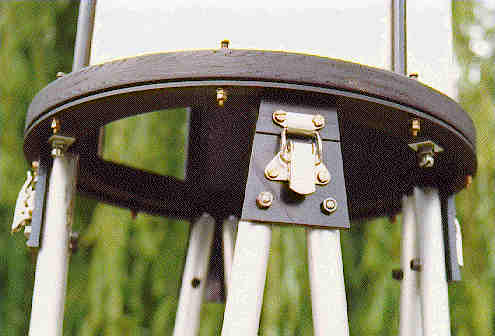 |
The 8 truss tubes are permanently bolted in pairs to four trapezium shaped plates just tight enough to allow them to swivel. The top-end unit gets clipped into position by four overcentre clips, forcing the ends of the truss pipes into the machined hollows at the correct angle, guided by locating pins. The friction ring as well as the tilt-adjustment screws and lock-nuts are again visible. This bottom plywood ring is actually two interlocking rings, machined with a step to fit within each other and separated by a Formica disk as a bearing. |

 Home |
CoSaTrak |
Site Map |
Telescope |
Historical |
Pictures |
Software |
Links |
Guestbook |