- Overview
- Sky Coverage
- Foci & Access
- Acquisition/Guider Boxes
- Acquisition & Autoguider Camera
- Visitor Instrumentation
This telescope was built by Grubb Parsons in 1938-48 for the Radcliffe Observatory, Pretoria. It has a 2-pier asymmetrical mounting. All observing is done with the telescope East of the polar axis; the telescope can no longer be used West of the pier.
| Cassegrain Focus: | f/18, ~6 arcsec/mm | SpUpNIC |
| Instrumentation: | GIRAFFE: Fibre-fed Echelle – currently unavailable | |
| HIPPO: Photo-polarimeter | ||
| SAAO CCD – currently unavailable | ||
| SHOC | ||
| Accessories: | Turntable, focal reducer | |
| Newtonian Focus: | f/4.85, 22.49 arcsec/mm | |
| Accessories: | Double Slide Plateholder | |
| Wynne Corrector | ||
| Finders: | 110 mm: 120 arcsec/mm, ~2 degree field | |
| 170 mm: 69 arcsec/mm, ~3/4 degree field | ||
Sky Coverage
Figure 1 shows the extent of the unvignetted visible sky when the telescope is east of the polar axis. Additional limitations apply in the case of certain instruments.
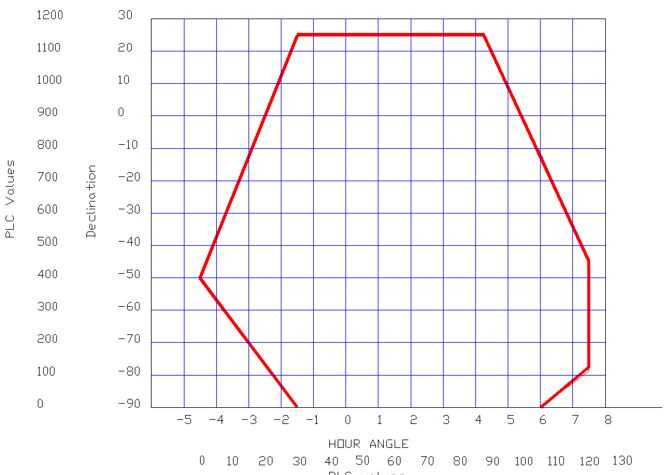
Figure 1. Observing limits for the 1.9-m telescope.
Foci and Access
Optical diagrams with relevant dimensions for the various foci are given in Figure 2. Observing with SAAO instruments is performed from the warm room. However, the Newtonian focus may be reached from a carriage which can be moved around the dome. Reaching the Cassegrain focus may require the observer to be as much as 4 m above the floor. Access is provided from a motorised x-y-z carriage whose platform is 1.42 x 1.98 m. There are also various ladders available.
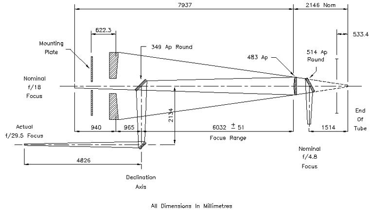 Figure 2: Optical Diagram
Acquisition/Guider Boxes
The acquisition box for instruments other than the grating spectrograph contains two 45° mirrors, one for offset guiding and one for rear viewing (Figure 3). These can be slid sideways pneumatically. The offset guiding mirror has an elliptical central hole with a 64 mm minor axis (giving a circular working aperture equivalent to 6.5 arcmin). The field of view for rear viewing is 4 arcmin. For autoguiding the same CCD detector is used as for acquisition, so the field of view will be the same as the acquisition TV field for the instrument in use. Stars for offset guiding should be bright enough to appear in the Hubble Guide Star Catalog, and must be located between 3′ and 7′ from the optical center. Difficulty in autoguiding may be experienced with stars brighter than 9th magnitude. A facility to mount a TV camera at the rear view focus is provided. There are bolt circles for attaching instruments to this acquisition box, as can be seen in Figure 4.
A similar acquisition/guider box (without rear viewing) is built into the spectrograph. The annulus for autoguiding is the same as given above.
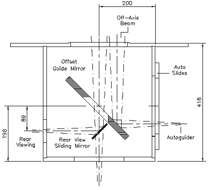
Figure 3. Acquisition/Guider box.
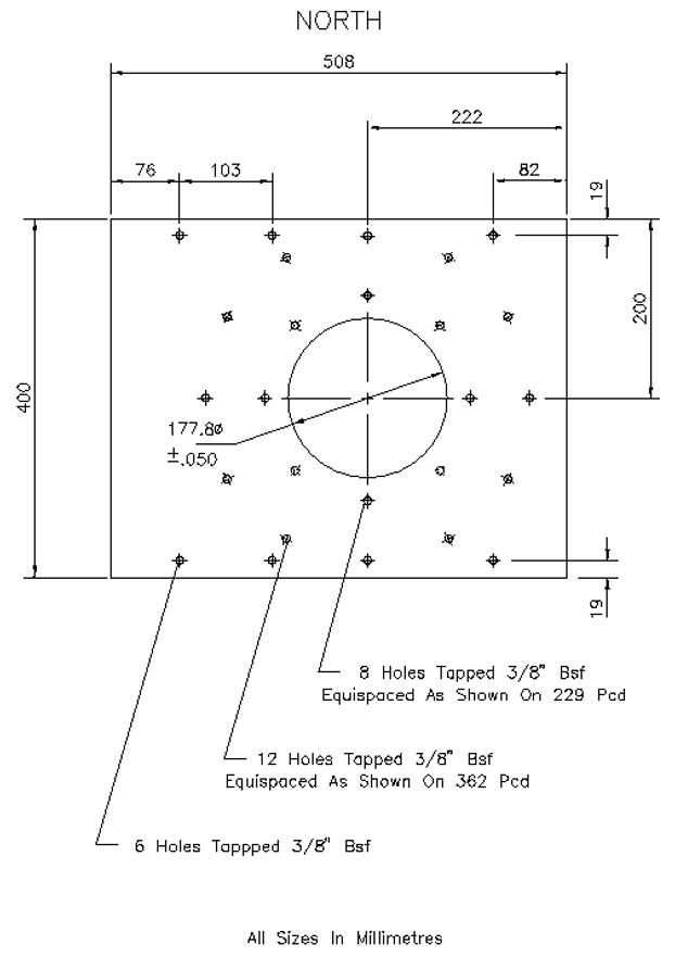
Figure 4. Acquisition box mount plate.
Acquisition & Autoguider Camera
The acquisition cameras/auto-guiders for the 1.9-m and 1.0-m telescopes at SAAO use 385 x 288 dye-coated EEV CCDs and are operated via transputer-based controllers. They have a broad wavelength response from roughly 0.35 to 1.0 µm with a peak around 0.7 µm.
Focal reducers for f/18 enable the acquisition camera to be used with the spectrograph on the 1.9-m telescope. The image scale is approximately 0.5 arcsec/pixel on both telescopes. Findercharts of 8×8 arcmin are appropriate.
For direct imaging using the SAAO CCD and UCT CCD, the acquisition cameras can be used together with the acquisition box and XY-slides. The spectrograph does not use the acquisition box.
Control Systems
There are separate drives for quick and slow motions on each axis. The R.A. fast drive is continuously variable; the declination fast motion utilises a two-speed motor.
The following slow-motion speeds are available:
R.A. set/guide 0 to 59.9999 arcsec/sec
R.A. trail 0 to 9.9999 arcsec/sec offset from track
R.A. track 0 to 29.9999 arcsec/sec
Dec. set/guide 0 to 39.9999 arcsec/sec
Observers wishing to use “trail” will need to arrange for the use of one of the “old” handsets.
Visitor Instrumentation
Special equipment is often difficult to mount and enquiries should be made well in advance. A special Cassegrain instrument mounting flange has been manufactured to accommodate instruments of up to 250 kg or less, with a versatile system of counterweights. Bolt circles are as shown in Figure 5. Figure 6 shows the filter box mount plate.
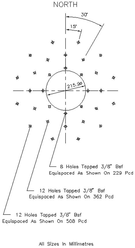
Figure 5. Cassegrain small instrument adaptor.
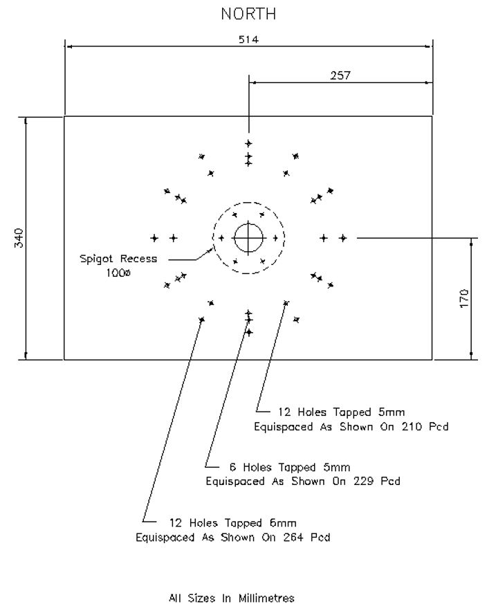
Figure 6. Filter box mount plate.